

Counters 4 - The carry chain
The carry chain is the feature allowing FPGAs to be efficient at arithmetic operations (counters, adders...). Let's learn more about carry chains using counters. Counters are easily built using T flip-flops.
A T flip-flop is very simple. At the clock rising edge, its Q output toggles if the T input is high, and doesn't change if T is low.
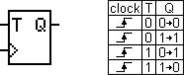
FPGAs use D flip-flops internally, but D and T flip-flops are easily interchangeable with a bit of logic around them. So we are using T flip-flops on this page, knowing that FPGA software can easily map them in the FPGA.
The ripple counter
The smallest binary counter is a ripple counter. Here's a 4bit ripple counter.
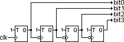
Basically each T flip-flop output drives the clock of the next flip-flop. It's very efficient in terms of hardware, but it's not great for FPGAs as we now have as many clock domains as there are bits in the counter. FPGAs are optimized for synchronous circuits, so we need something where all the counter bits toggle at the same time.
The synchronous counter
In a synchronous counter, the clock feeds all the flip-flop simultaneously, so there is only one clock domain.
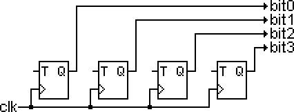
Now, if we look at the way a binary counter counts, we see that the bit0 always toggles and that for any higher bit to toggle, all the bits of lower order need to be 1. So our synchronous counter takes shape by using a few AND gates.
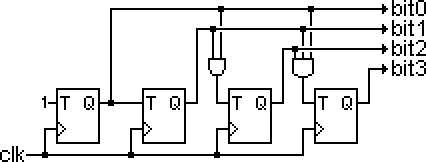
It's good as long as the counter is small. Our example 4bit counter only needs two AND gates (plus the flip-flops obviously) so it's pretty efficient. But that doesn't scale well. For a 32bit counter, we would need 30 AND gates, the last one having 31 inputs... However we can easily redraw our counter this way (we made a 6bit counter this time).

Basically instead of having AND gates grow in size, we keep them small and chain them.
That's the way FPGAs implement counters. It is efficient in term of hardware but the problem is speed... For example, a 32bit counter would need 30 chained AND gates. And this chain is the main part of the counter "critical path" (which sets the maximum counter clock speed). So it is important to keep this path fast... and FPGAs have one nice trick to keep it fast. It is called...
The carry chain
FPGAs are made of "logic elements", each containing one LUT and one D flip-flop. Each logic element can implement one counter bit (a 32bit counter needs 32 logic elements).
Logic elements can communicate with their surroundings through general-purpose routing structures, but that's slow. So FPGA designers made sure that logic elements placed side by side have an extra local routing signal.

is implemented as
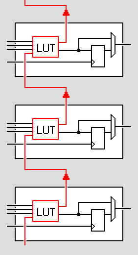
This local routing is often used as a carry chain. Every time you ask the FPGA software to implement a binary counter, it maps the bits next to each other so that it can use the local routing as a carry chain. That adds a bit of constraint on the mapping, but the software takes care of it.
FPGA manufacturers also make sure that logic elements are heavily optimized for speed along the carry chain path. The result is counters that run easily at hundred of MHz... the speed of counters is usually not an issue (the critical path of an FPGA design is much more likely to go through regular logic than carry chains). Of course, it depends on how fast you want to run your design. Big counters feature long carry chains, and so cannot be clocked as fast as small counters. If that's an issue, you can either break down the carry chains (i.e. use a series of small counters) or choose a counter architecture that doesn't use carry chains.
For those adventurous, click here for an ISE FPGA editor screenshot of a slice (two logic elements) from a Spartan-3A FPGA design implementing a counter. The view is for bits 6 and 7 of the counter. We can immediately recognize the carry chain crossing the slice in the middle from bottom to top. What is less apparent is where are the AND gates and the T flip-flops. They are actually all there... the AND gates are made using the big muxes on the carry chain line and the T flip-flops are made using XOR gates and the D flip-flop outputs that loop back to the LUT inputs (through routing outside the logic elements). The LUTs are just pass-through.
Carry chains are also used for adders and comparators. But thanks for the hundred of engineers working to build smart HDL tools, we can use the power of carry chains without having to worry about them. Life is good.