

R/C Servos
FPGAs are suitable to control R/C Servos.
What is an R/C Servo?
An R/C Servo ("remote control servo motor") consists of a motor, some electronics, and a set of gears enclosed into a small box. A single axis comes out of the servo. You control precisely the angle of rotation of the axis by sending pulses to the servo. The axis rotational angle is limited to about 270 degrees (it cannot make a complete turn, but only 3/4 of a turn).
Here's a picture of one servo (old and bitten up, but illustrates our purpose).
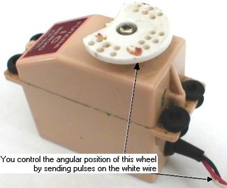
Useful informational links include: R/C Servos are used in:
- In remote controlled models (cars, airplanes...).
- In robotics.
Electrical connection and PWM pulses
Servos have 3 wires:- Black: ground.
- Red: power supply (+5V).
- White: rotation control (using PWM).
A pulse of 1.5ms rotates the axis in the middle of its rotation range.
A new pulse needs to be sent regularly (every 10 to 20ms), even if the angular position doesn't need to be changed, or the servo will stop trying to hold it.
PWM pulses from an FPGA
Let's control a servo with an 8 bits resolutions (256 steps, from 0 to 255). That means that we need to generate a pulse from 1ms (0) to 2ms (255), with a resolution of 1ms/256=3.9µs.Dividing the clock
Using a 25MHz clock (40ns period), the first step is to divide the clock to generate a "tick" of period as close as possible to 3.9µs.|
parameter ClkDiv = 98; // 25000000/1000/256 = 97.56 reg [6:0] ClkCount; reg ClkTick; always @(posedge clk) ClkTick <= (ClkCount==ClkDiv-2); always @(posedge clk) if(ClkTick) ClkCount <= 0; else ClkCount <= ClkCount + 1; |
Using the "ClkTick", we instantiate a 12-bits counter that increments at every tick.
|
reg [11:0] PulseCount; always @(posedge clk) if(ClkTick) PulseCount <= PulseCount + 1; |
Each tick lasts 3.9µs, so 256 ticks lasts 1ms, and the 12 bits counter "PulseCount" rolls-over every 16ms. Just what we need to generate a new pulse regularly.
Generating the PWM pulse
We start each pulse when "PulseCount" equals 0.We end each pulse when "PulseCount" is somewhere between 256 and 511. That generates the pulse between 1ms and 2ms.
Assuming that "RCServo_position" is the 8 bits position value (from 0 to 255), we concatenate a "0001" in front of it to create a 12 bits value ranging from 256 ot 511. Finally, we compare these 12 bits to "PulseCount" to generate the pulse.
|
reg RCServo_pulse; always @(posedge clk) RCServo_pulse = (PulseCount < {4'b0001, RCServo_position}); |
That's all folks! The complete code can be found here.
As you can see, it takes very little hardware to control an R/C servo, so an FPGA could control multiple of them simultaneously.