
FPGA software 2 - FPGA design entry
There are 2 methods:
- Using a schematic.
- Using an HDL (Hardware Description Language).
Schematic design entry
With schematic design entry, you draw your design on your computer using gates and wires.
Schematic entry is nice because it documents the design in an easily readable format. But big designs quickly become difficult to maintain, the file formats are incompatibles between vendors, and HDLs are easier to parameterize, so many FPGA users quickly shy away from schematic design entry.
HDL design entry
Vendors used to have proprietary languages. But then came two HDL languages (VHDL and Verilog) that quickly got popular. Now FPGA vendors support mainly these two languages.
Learning an HDL takes an effort, and this is probably the most important thing you'll have to learn when diving into the FPGA world. This website makes it somehow easier since you can learn from examples. And your time-investment is protected because these languages are now industry standards.
How do HDLs look?
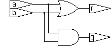
Ok, let's implement a set of AND and OR gates, like that:

The HDL code looks like that:
| Verilog | VHDL |
|---|---|
|
module gates(a, b, q, r); input a, b; output q, r; assign q = a & b; assign r = a | b; endmodule |
library ieee; use ieee.std_logic_1164.all; entity gates is port( a,b: in std_logic; q,r: out std_logic); end; architecture implement of gates is begin q <= a and b; r <= a or b; end; |
Now let's look on how to create a D flip-flop:

| Verilog | VHDL |
|---|---|
|
module d_flipflop(clk, d, q); input clk, d; output q; reg q; always @(posedge clk) q <= d; endmodule |
library ieee; use ieee.std_logic_1164.all; entity d_flipflop is port( clk, d: in std_logic; q: out std_logic); end; architecture implement of d_flipflop is begin process(clk) begin if clk'EVENT and clk='1' then q <= d; end if; end process; end; |
With both languages, notice how the D flip-flop is expressed by its behavior (i.e. at each positive clock edge, copy the 'd' input to the 'q' output). VHDL and Verilog are called "behavioral languages" because of that.
These two examples are synthesizable (you can directly put them into an FPGA), but behavioral languages can also produce...
Non-synthesizable designs
Using a behavioral language, you can describe a circuit that has no hardware equivalent. For example a flip-flop that takes 2 clocks can be simulated but not synthesized.
|
module d_flipflop_2clks(clk1, clk2, d, q); input clk1, clk2, d; output q; reg q; always @(posedge clk1 or posedge clk2) q <= d; endmodule |
VHDL or Verilog?
Although advanced users might have specific needs (like VHDL's advanced type structures, or Verilog's "PLI" interface), which language to use is often a matter of preference (and politics if you do it for a living). For this website, we favor Verilog as it's a bit easier to learn than VHDL.
SystemVerilog is an extension of Verilog that seems to be gaining industry acceptance (tries to merge the best of VHDL and Verilog).
Links
- A SystemVerilog for FPGAs from Sutherland HDL.
- A (bit dated) white paper from Mentor Graphics.
- Make your own opinion using a Google search.