

Hands-on - A digital oscilloscope
Let's build a simple digital oscilloscope.
- Single channel, about 100 MSPS (mega-samples-per-second)
- RS-232 based (we'll look into USB too)
- Inexpensive!
A simple digital oscilloscope recipe
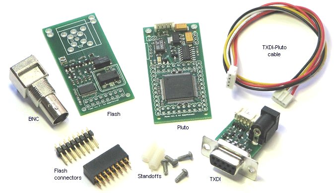
Using parts from KNJN.com, here are the basic items of our recipe.- 1 x Pluto FPGA board, with TXDI and cable (item#6120 and #6130 = $36.90)
- 1 x Flash 100MHz acquisition board (item#1206 = $39.95)
- BNC connector + nylon standoffs + connectors 2x8 (item#1250 + #1270 + #1275 = $10.85)
Here's how they look.
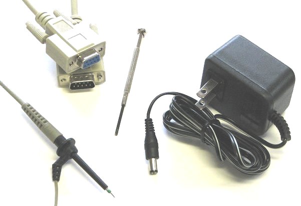
- A small DC adapter 5V to 9V, 100mA or more.
- An RS-232 extension cable.
- A little screwdriver.
- And of course, an oscilloscope probe.
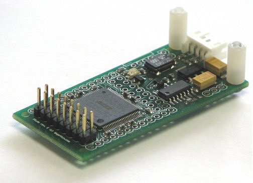
1. Pluto
The male connector needs to be soldered on Pluto.
Let's also screw-in the two standoffs.
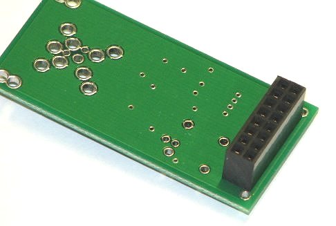
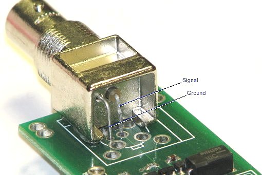
2. Flash
Now for Flash. The female connector goes on Flash's bottom. Place it and solder it there.
The BNC goes on Flash's top. Let's make sure the BNC signal and ground leads go into the right spots.
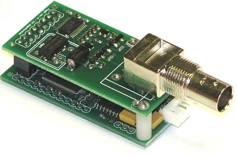
3. Pluto and Flash combo
With the connectors soldered, the two boards mate easily, and the top standoff screws can be added.
4. Let's power it up
Now TXDI can be connected to Pluto. We add the RS-232 connection to a PC, the 9V (or so) power adapter, and the oscilloscope probe on the BNC.
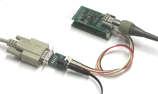
We are ready to probe!
5. The software
Let's run the Flash software provided with Pluto.
First we get a flat trace.
Let's probe something.
We fire up our signal generator, select triangular signal, here it is!
6. Possible improvements
Here are a few ideas:- Use a Pluto-II instead of a Pluto (Pluto-II has a boot-PROM so can be active at power-up, and the bigger FPGA allows more features in the oscilloscope). Or even a Pluto-3 and a FlashyD to get a two channels oscilloscope. Or use a different Flashy revision - for example rev. K allows precise frequency measurements and equivalent-time sampling.
- Make the oscilloscope USB-based (see here) or use a Saxo or Xylo board instead of a Pluto (which are natively USB controlled/USB-powered, and support FlashyD = two channels).
- Another possibility is to add an LCD (like KNJN item#5300) but don't use a Pluto FPGA board in this case (it wouldn't work because its FPGA is too small to drive the LCD while the oscilloscope is running).