
Serial interface 3 - RS-232 transmitter
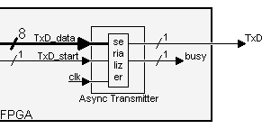
We are building an "async transmitter" with fixed parameters: 8 data bits, 2 stop bits, no-parity.

It works like that:
- The transmitter takes an 8-bit data inside the FPGA and serializes it (starting when the "TxD_start" signal is asserted).
- The "busy" signal is asserted while a transmission occurs (the "TxD_start" signal is ignored during that time).
Serializing the data
To go through the start bit, the 8 data bits, and the stop bits, a state machine seems appropriate.
|
reg [3:0] state; // the state machine starts when "TxD_start" is asserted, but advances when "BaudTick" is asserted (115200 times a second) always @(posedge clk) case(state) 4'b0000: if(TxD_start) state <= 4'b0100; 4'b0100: if(BaudTick) state <= 4'b1000; // start 4'b1000: if(BaudTick) state <= 4'b1001; // bit 0 4'b1001: if(BaudTick) state <= 4'b1010; // bit 1 4'b1010: if(BaudTick) state <= 4'b1011; // bit 2 4'b1011: if(BaudTick) state <= 4'b1100; // bit 3 4'b1100: if(BaudTick) state <= 4'b1101; // bit 4 4'b1101: if(BaudTick) state <= 4'b1110; // bit 5 4'b1110: if(BaudTick) state <= 4'b1111; // bit 6 4'b1111: if(BaudTick) state <= 4'b0001; // bit 7 4'b0001: if(BaudTick) state <= 4'b0010; // stop1 4'b0010: if(BaudTick) state <= 4'b0000; // stop2 default: if(BaudTick) state <= 4'b0000; endcase |
Now, we just need to generate the "TxD" output.
|
reg muxbit; always @(state[2:0]) case(state[2:0]) 0: muxbit <= TxD_data[0]; 1: muxbit <= TxD_data[1]; 2: muxbit <= TxD_data[2]; 3: muxbit <= TxD_data[3]; 4: muxbit <= TxD_data[4]; 5: muxbit <= TxD_data[5]; 6: muxbit <= TxD_data[6]; 7: muxbit <= TxD_data[7]; endcase // combine start, data, and stop bits together assign TxD = (state<4) | (state[3] & muxbit); |
The complete code can be found here.