

10BASE-T FPGA interface 1 - How Ethernet works
This is a short introduction to the Ethernet technology.
If you are new to it, you can get more details from Charles Spurgeon's Ethernet web site.
The comments on this page apply equally for 10BASE-T and 100BASE-T (the later being 10 times faster).
The standard is freely available on the IEEE 802.3 Standards Association page. If you want a copy, select the latest standard "IEEE 802.3-2002". Relevant chapters include chapter 3 (MAC frame structure) and 14 (10BASE-T).
They look like that:
Out of the 8 pins, only 4 are used:
Note: This pinout is good for the RJ-45 coming out of your computer. The pinout of a hub or switch is inverted (TD on pins 3 & 6, and RD on pins 1 & 2).
The Ethernet is based on the idea of a shared medium - if a station sends a packet, everybody on the line receives it. Each Ethernet card has a unique ID (the "MAC address"), so each card can automatically discard packets meant for another station. The MAC address is 6 bytes long (48 bits), which is big enough to allow each Ethernet card on earth to have a unique number!
Half-duplex uses a protocol called "CSMA/CD" (Carrier Sense Multiple Access with Collision Detection):
In half-duplex:
Full-duplex communication is better:
There are two types of concentrator available: "hub" or "switch".
This project recommends the use of a full-duplex links, because it doesn't implement CSMA/CD. Using half-duplex links would still work, but at the cost of potential packet losses (especially when using a hub-ed shared medium).
If you are new to it, you can get more details from Charles Spurgeon's Ethernet web site.
The comments on this page apply equally for 10BASE-T and 100BASE-T (the later being 10 times faster).
IEEE 802.3
The 10/100BASE-T interface is described in the IEEE 802.3 standard.The standard is freely available on the IEEE 802.3 Standards Association page. If you want a copy, select the latest standard "IEEE 802.3-2002". Relevant chapters include chapter 3 (MAC frame structure) and 14 (10BASE-T).
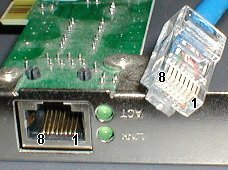
RJ-45 connectors
10/100BASE-T uses RJ-45 8 pins connectors.They look like that:
Out of the 8 pins, only 4 are used:
- TD+ (transmit +)
- TD- (transmit -)
- RD+ (receive +)
- RD- (receive -)
Note: This pinout is good for the RJ-45 coming out of your computer. The pinout of a hub or switch is inverted (TD on pins 3 & 6, and RD on pins 1 & 2).
Differential signal
Each pair uses a differential electric signal (differential signals are more immune to external interferences). Also each wire pair is twisted in the cable, which further improves the immunity.Packet encoding
To send data on Ethernet, you cannot just send it like that; you have to encapsulate it into an Ethernet packet. The packet contains a header with the information necessary for the data to reach its destination.The Ethernet is based on the idea of a shared medium - if a station sends a packet, everybody on the line receives it. Each Ethernet card has a unique ID (the "MAC address"), so each card can automatically discard packets meant for another station. The MAC address is 6 bytes long (48 bits), which is big enough to allow each Ethernet card on earth to have a unique number!
Half-duplex versus Full-Duplex
Ethernet was originally built using a truly shared medium (a single coaxial cable connected to several stations). The same cable was used for both transmission and reception. So of course, you could not transmit and receive at the same time. Communication was half-duplex.Half-duplex uses a protocol called "CSMA/CD" (Carrier Sense Multiple Access with Collision Detection):
In half-duplex:
- Before transmitting, each station has to listen to make sure the line is free ("Carrier Sense").
- Still, it is possible that two stations transmit just at the same time. So a complex protocol has to exist to abort ("Collision Detection") and resume transmission later.
Full-duplex communication is better:
- You get twice the bandwidth.
- Each station has a dedicated medium and can start transmitting at any time without complication (CSMA/CD doesn't apply anymore).
Hubs and Switches
10/100BASE-T is a "star-topology" network. It requires the use of a concentrator appliance to connect multiple computers together.There are two types of concentrator available: "hub" or "switch".
- A hub is a simple electronic device that provides electrical separation between each link but still connects them "logically" together. That forces the communication to be half-duplex. Worse: at any given time, only one computer can speak. So the network bandwidth is shared among all the computers.
- A switch (or "switching-hub") is a more complicated electronic device that isolates each computer link both electrically and logically. It does that by storing internally each transmitted data before re-transmitting it. So each computer can speak whenever he wants: that allows full-duplex communication. Even better: each computer has a full link bandwidth for itself. And since the medium is not shared, each station receives only the packets intended to itself (privacy is improved).
- Hub-ed: half-duplex on each link, with 10Mbps shared among all the computers. Slow...
- Switch-ed: full-duplex on each link, with 20Mbps (10Mbps each way) dedicated for each computer. Fast!
This project recommends the use of a full-duplex links, because it doesn't implement CSMA/CD. Using half-duplex links would still work, but at the cost of potential packet losses (especially when using a hub-ed shared medium).
Links
You can find more details on these pages:- Introduction to switch technology (PDF) from Contemporary Control Systems, Inc.